Engine bearing installation tips
When taking bearing measurements, they should always be taken at 90-degrees to the parting line to determine the minimum clearance. If measuring the bearing wall thickness, use a special micrometer with a ball anvil to fit the curvature of the bearing ID. The best way to determine bearing clearance is to measure the bearing ID with the bearings installed in the housing and the bolts torqued to the specified assembly torque. Use a dial bore gauge to measure the bearing ID at 90-degrees to the parting line, then subtract shaft size from bearing ID to determine the clearance. If the dial bore gauge is zeroed at the actual diameter of the crankshaft journal to be installed, the dial bore gauge will then read clearance directly and the subtraction calculation can be eliminated. About .001" clearance per inch of shaft diameter is a good rule of thumb. Increasing that by about .0005" will add a little margin of safety when starting out, especially for rods. Example: .001" X 2.100 = .0021" then add .0005", so starting out set clearance at .0026" for a 2.100 shaft.
If clearance adjustments need to be made, use either an extra clearance part for more clearance or an undersize part for less clearance. It is permissible to mix sizes if less than .001" adjustment in clearance is desired. When mixing sizes for a select fitting: a) never mix parts having more than .0005" difference in wall size; b) and always install the thickest wall shell in the upper position if installing a rod bearing or the lower position if installing a main bearing. When working with a reground shaft, always measure assembled bearing ID's first. Next have a shaft sized to produce the desired clearance since there are no extra clearance parts available for undersize shafts.
When measuring a bearing ID or wall thickness, avoid measuring at the parting line. The diagram illustrates there is a parting line relief machined into nearly all bearing shells. This relief is to allow for any mis-match between upper and lower shells due to tolerance differences, or possibly resulting from cap shift or twist during assembly. To determine bearing wall eccentricity or assembled bearing ID ovality, measure at a point at least 3/8" away from the parting line.
When installing any bearing DO NOT ATTEMPT TO POLISH THE BEARING RUNNING SURFACE WITH ANY TYPE OF ABRASIVE PAD OR PAPER. Bearing overlay layers are extremely soft and thin – typically .0005" on high performance parts. These thin layers can easily be damaged or removed by an abrasive media. Because the overlay layer is electroplated, it may exhibit microscopic plating nodules that make it feel slightly rough. The nodules are the same material as the rest of the plated layer and will quickly be flattened by the shaft. Bearing surfaces can be lightly burnished with solvent and a paper towel if desired.
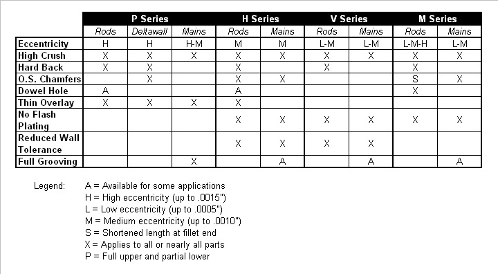
Arriving at the correct choice of a high performance bearing for any given racing application is much like determining what clearance works best. From past experience, our knowledge of the intended usage and common sense can guide us in making an initial choice. Next, we can fine tune the selection process based on those results. The information given here is intended to aid in the initial selection as well as the fine tuning process.